
For my mixed-signal VLSI course, I was tasked with designing and laying out a 4-bit shift register while optimizing for cell width using the open-source Sky130 PDK. To do this, I first needed to design the basic element of a shift register: the D flip-flop.
I decided to go with a CSRL latch for my design due to its relatively small transistor count and it's relaxed requirements for transistor sizing. My main consideration was the relative strength ratio of the pass transistors to the PUN and PDN. Since MOSFETs are bidirectional devices, this ratio needs to be higher than around 2 for this technology in order to ensure data doesn't flow backwards. I chose a value of 3 to ensure safe noise margins. I ended up creating a layout-driven schematic to assist later in the process.
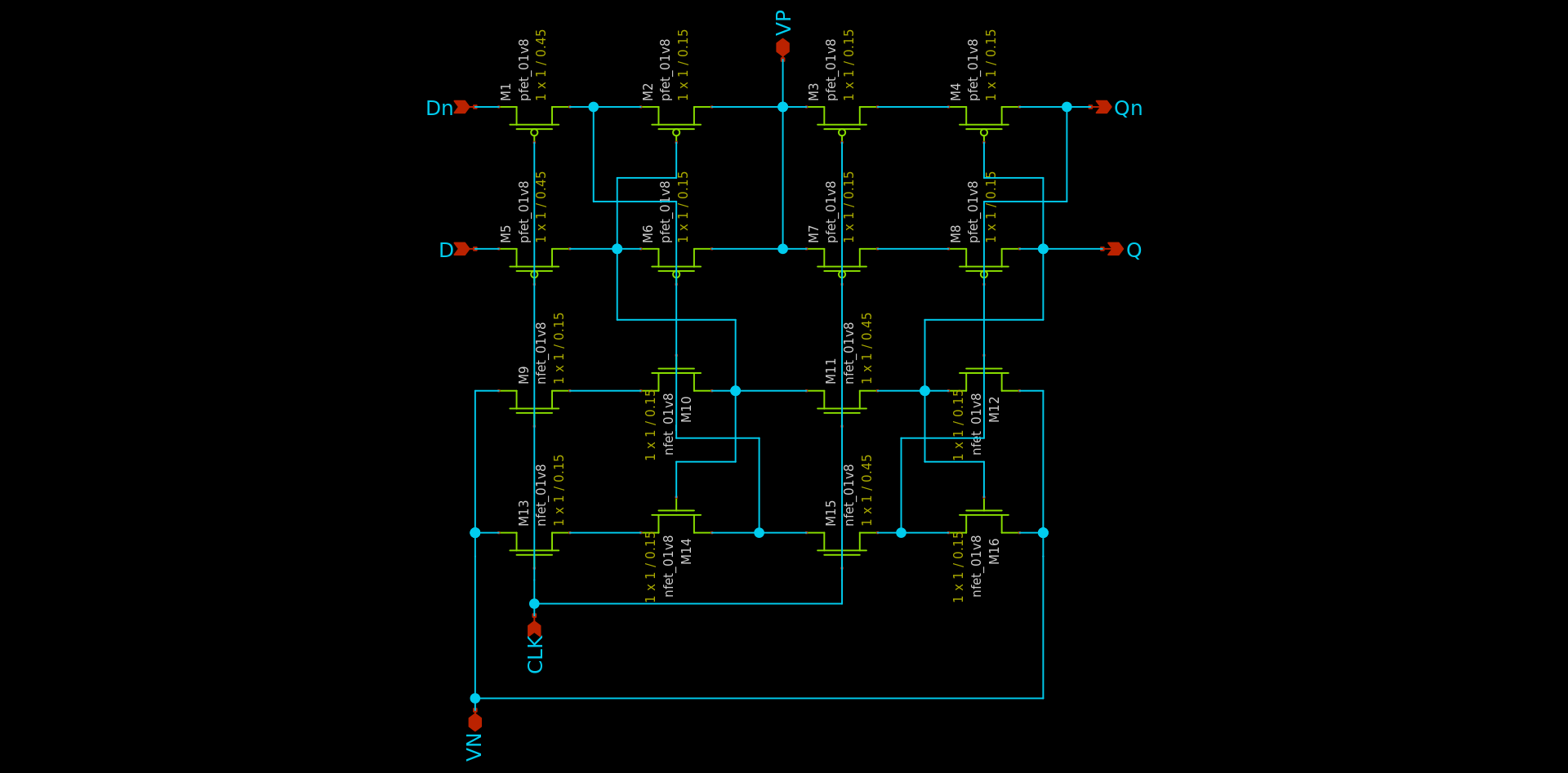
D flip-flop Schematic
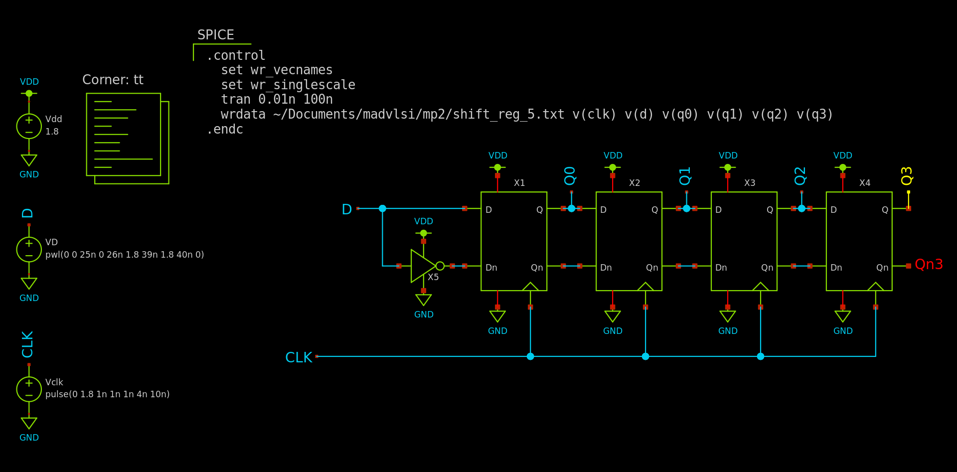
I then chained four of these together to create a shift register. I performed corner analysis using the PDK corner models to ensure proper operation across process variation.
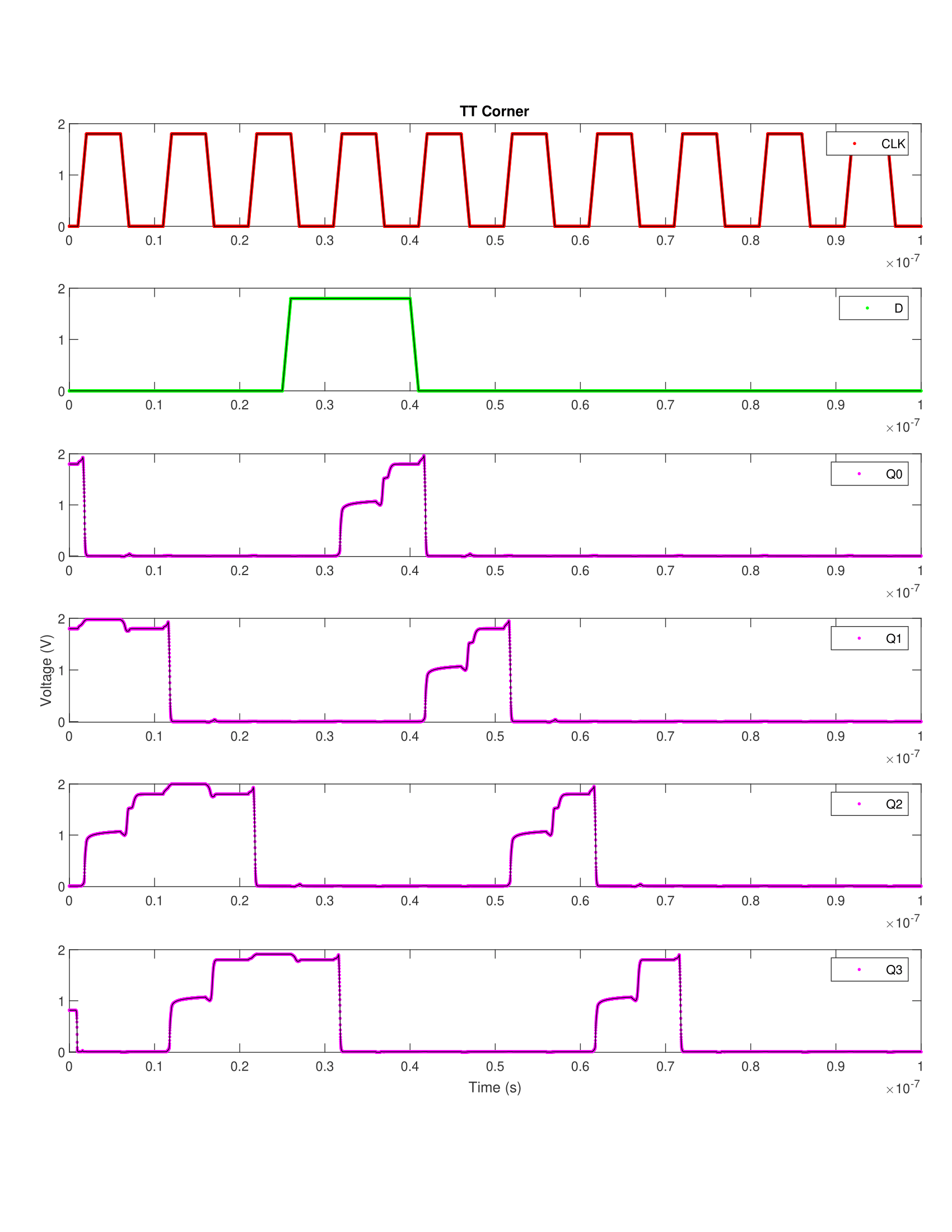
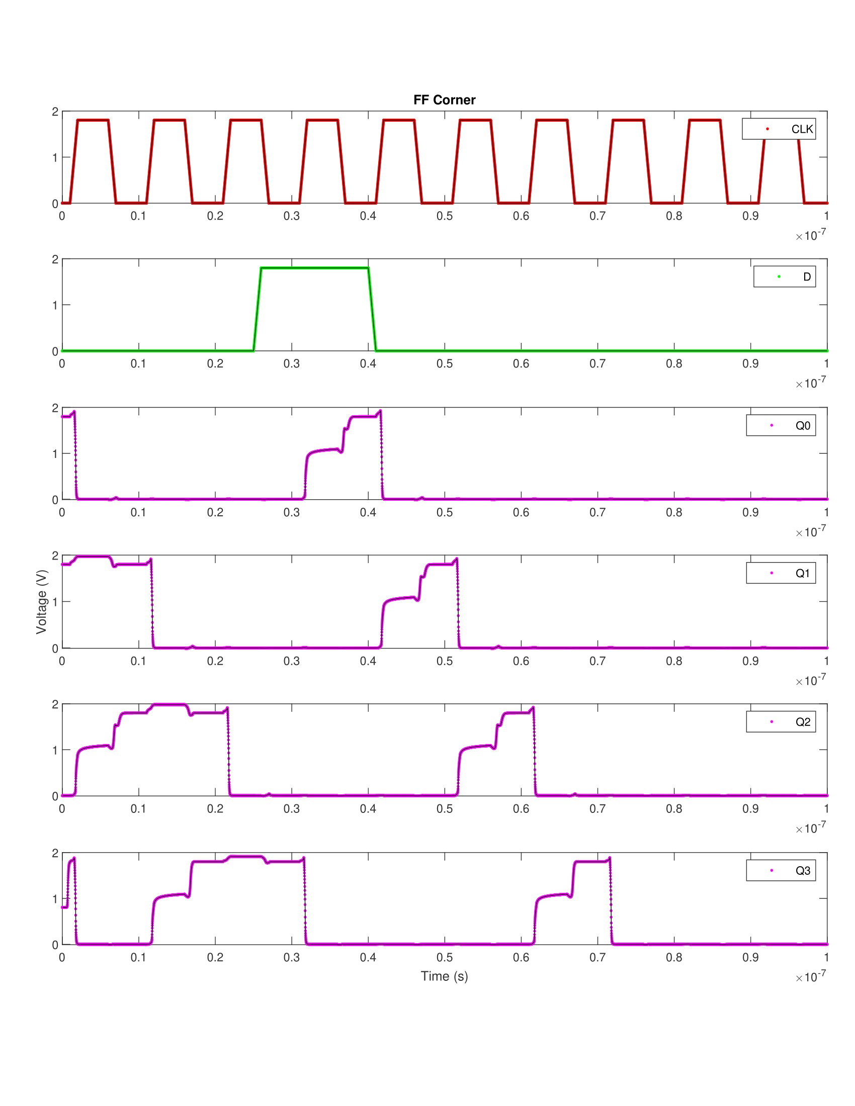
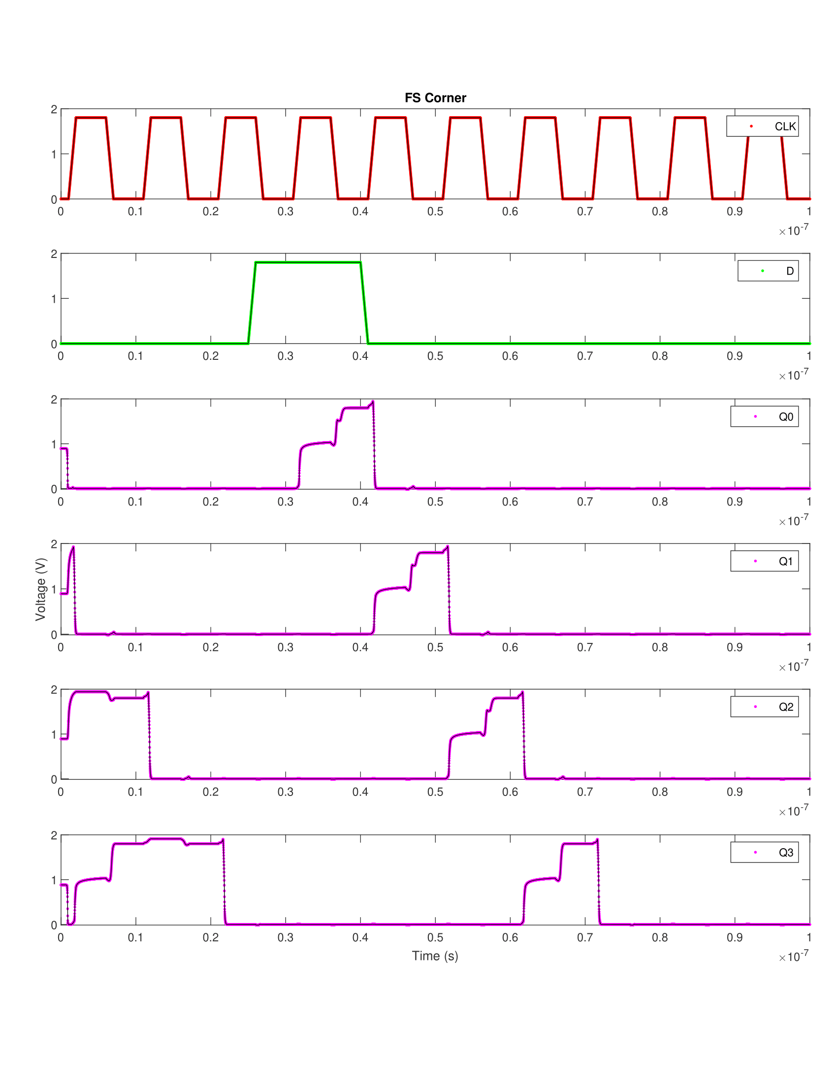
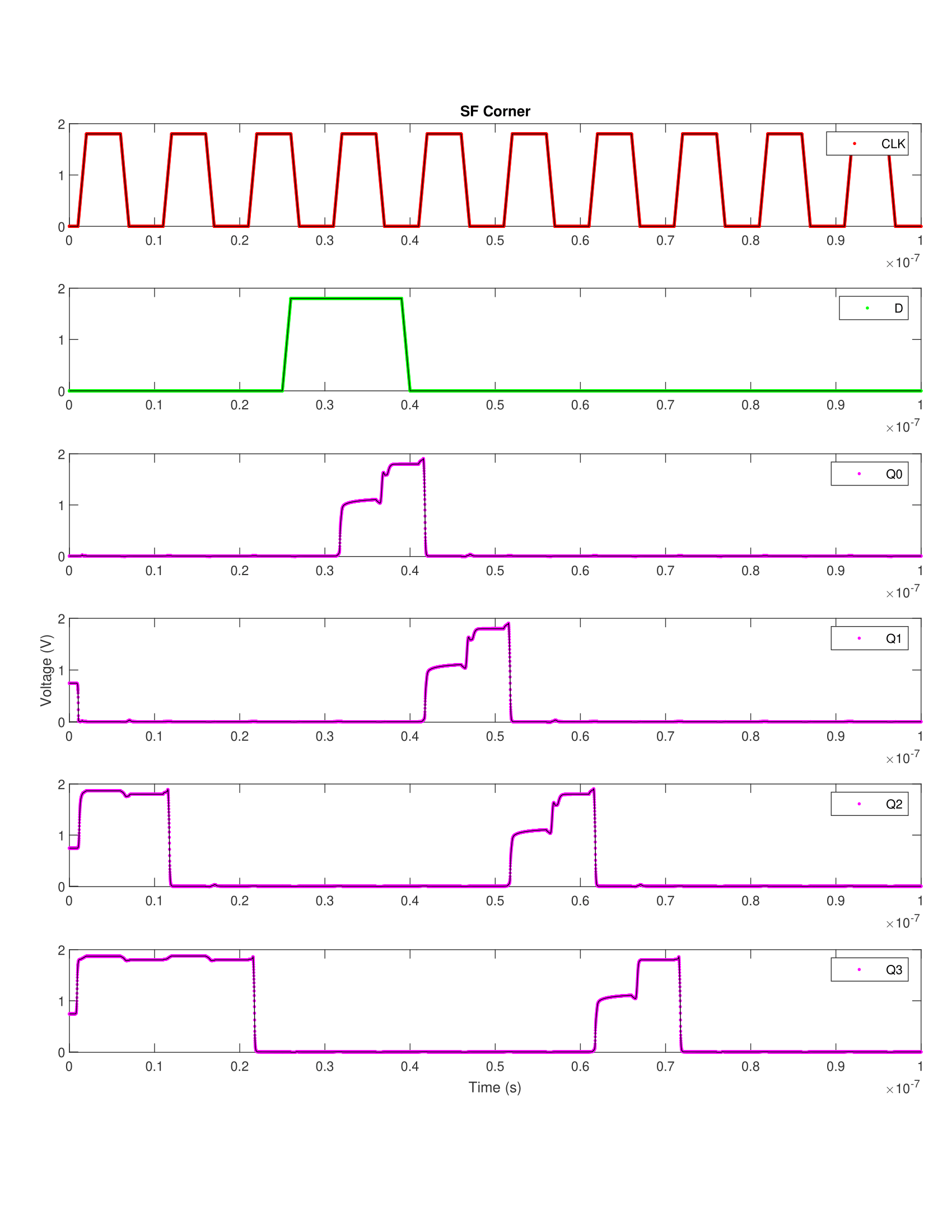
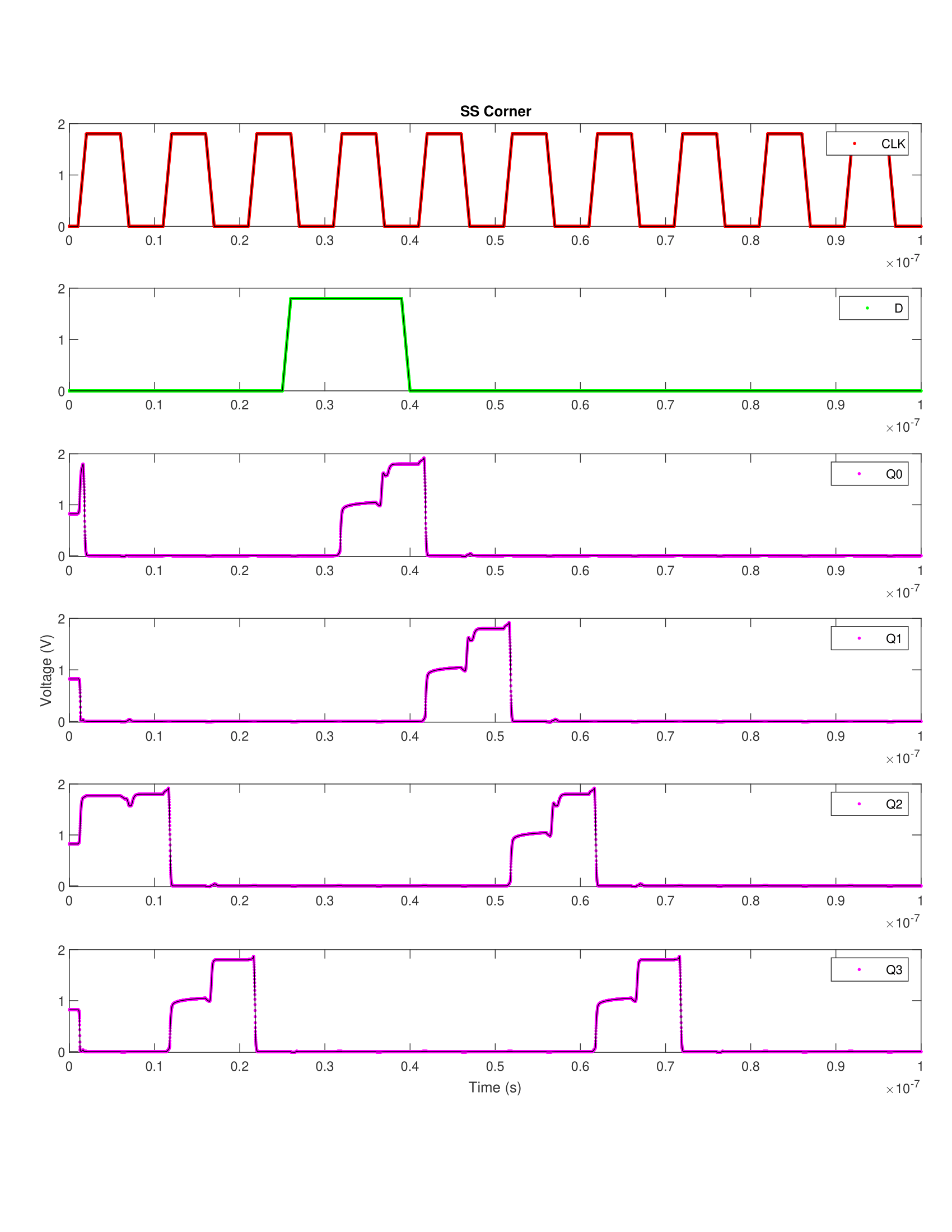
As you can see, there's a stair-stepping behavior in the output when a flip-flop latches a 1. This is because the pass transistors can only pass a weak 1 before the cross-coupled inverters kick in and restore the logic level. In my case, this was an acceptable tradeoff.
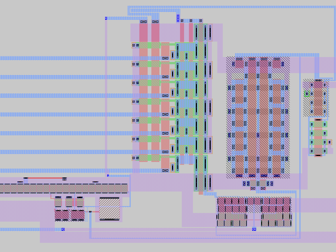
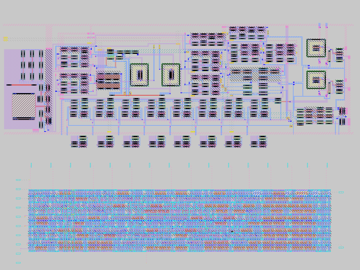
My next step was to turn my schematic into a layout. I decided to go with a standard-cell style layout because it would allow me to easily adjoin my modules. We use the program Magic to do layout. I managed to fit my D flip-flop into just 3.70 x 8.35 microns!
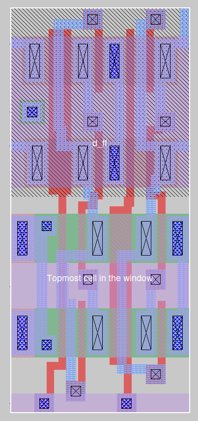
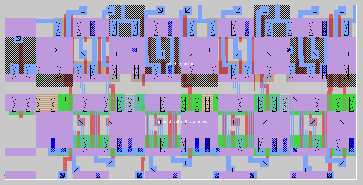
I then put four of these next to each other and added an inverter to generate the inverted data input required by the shift register. My final layout was 16.850 x 8.35 microns.
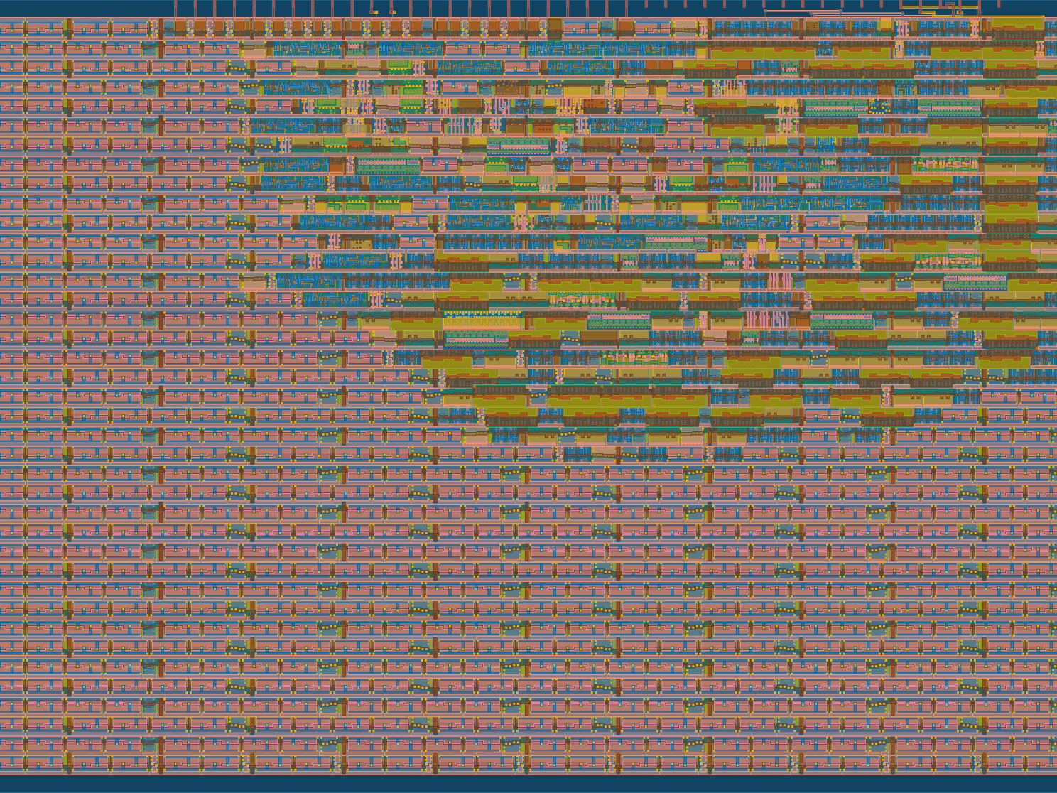
Lastly, I extracted SPICE netlists from both my schematic and my layout and performed LVS on them to determine if what I had drawn actually matched what I had designed. We use a tool called netcomp (which is part of the OSS CAD suite). The tool was able to verify that my circuits matched uniquely without any property errors, meaning that my layout was correct.
This was a very engaging project that had me work at a lot of different levels of abstraction. I learned about digital layout, the VLSI toolchain, and how to design circuits and test circuits for ICs.